


| CONTRIBUTE |
"On this site, a powerful engine will be built... an engine that will someday help us to travel a hundred times
faster than we can today. Imagine it: thousands of inhabited planets at our fingertips. And we'll be able to
explore those strange new worlds... and seek out new life and new civilizations. This engine will let us go
boldly... where no man has gone before." ~ Dr. Zephram Cochrane, 2119
The key to modern and efficient space travel is the ability to combine superior warp field generation with efficient
power generation. Through key research and design, the Warp Five Complex has accomplished this task while
revolutionizing human space travel.
The Warp Five Complex, or now named Theoretical Propulsion Complex, was founded in 2119 in Bozeman,
Montana by Dr. Zephram Cochrane and Henry Archer with the goal of creating an engine that would transform our
pioneering sojourns into the cosmos. Limited to a timid warp two, much of human exploration was confined to a
very small corner of the galaxy and local trade routes. Mankind desperately needed something faster and more
technologically advanced to properly begin to explore. The team at the Theoretical Propulsion Complex
concentrated much of their research and development efforts into finding ways to improve the efficiency and
hardware of Cochrane’s original warp drive design. Through inventive fabrication techniques, new research into
metallurgy, computer control architecture, and dilithium crystal research, the Complex staff was able to produce a
significant breakthrough with a functional Warp Five Engine.
After the success of the Warp Five Engine, the staff and administrators of the Theoretical Propulsion Complex
forged ahead with producing new technological advances. By concentrating research efforts on field coil refinement,
plasma acceleration, and a more stable reactant injector, the group began refining the Warp Five technology into
something even faster. In 2156, the Theoretical Propulsion Complex introduced a new Warp Seven Engine and
installed it as part of a refit to the Enterprise NX-01, allowing us to continue to “boldly go” as Dr. Cochrane predicted.
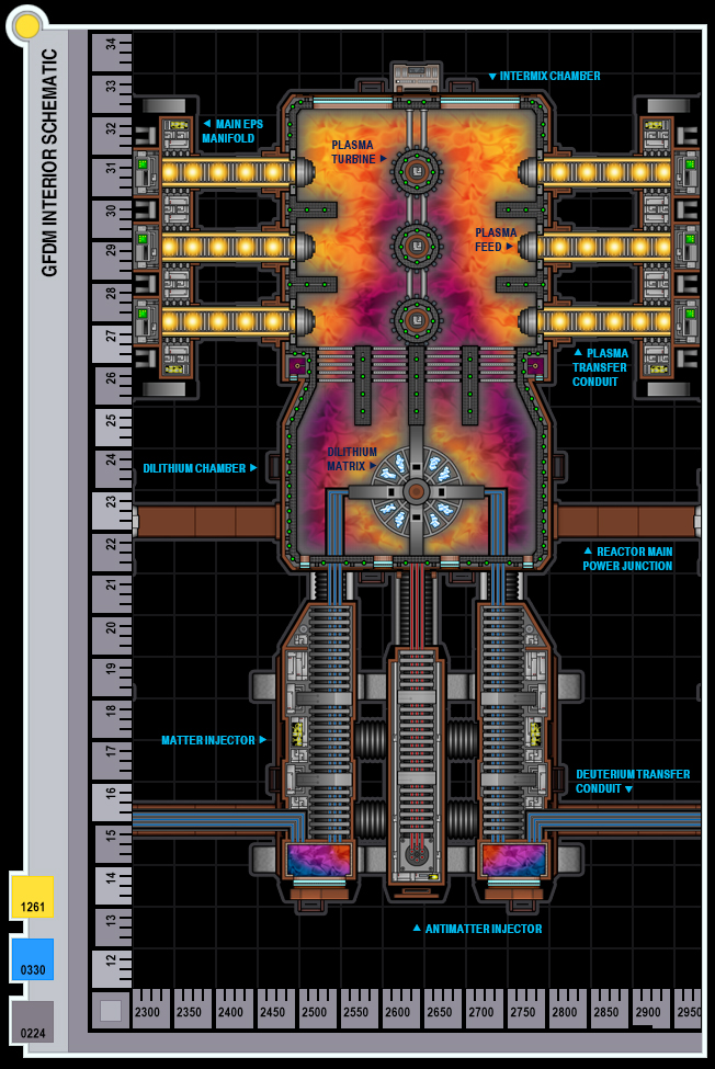
THE GRAVIMETRIC FIELD DISTORTION MANIFOLD
Located on Deck 10, the Gravimetric Field Displacement Manifold or Main Reactor Core is the primary power plant
onboard the NX-01. Its copper-colored flattened cylindrical shape measures 3.65 meters high, 5.64 meters wide
and 16.6 meters long and occupies a special three-story compartment within the Refit Engineering Hull. The
reactor is broken down into four separate components: the matter/antimatter injectors, the dilithium manifold,
dilithium chamber or reaction chamber, and intermix chamber. Each separate component is contained within the
core’s cylindrical shape by a shielded outer hull approximately thirty-eight centimeters thick.
THE GFDM OUTER HULL
The outer hull of the GFDM is made up of three separate layers: the outer skin, support trusses/insulating vacuum
layer, and the inner shielding layer. Each layer is engineered to insure proper containment and maximum stability of
the reactor core.
The outer skin is composed of a copper-duritanium alloy approximately eight centimeters thick. This outer layer is
designed to be a redundant safeguard against radiation while maintaining the structural integrity of the core
envelope.
The second layer, or support layer, is made up of structural braces and cross members used to form the core’s
rigid structure. These structural pieces are composed of ditanium and a special beryllium-titanium alloy both
formulated to withstand the heat and pressure produced by the core. To insulate against thermal variations the
empty spaces found between the structure and the outer skin are decompressed to form a vacuum.
The inner layer of the core, at twenty centimeters, is the thickest and most important of the three. Constructed from
carbogermanium, this layer’s ceramic composite material is capable of withstanding high temperatures while
insulating against harmful radiation. Imbedded into this layer is a network of coolant conduits and magnetic
containment segments. The coolant controls the amount of radiant energy produced within the core and is fed from
below through conduits contained within reactor’s support struts. Coolant is moved through the system at thirty
liters per second and is reduced or increased automatically depending on the reactor’s needs through six
redundant pumping stations located at the rear of the Engineering compartment. The magnetic containment
segments safely maintain the reacting plasma until it can be transferred to the nacelles or EPS grid for use.
Composed of cobalt-boronite, each segment produces an internally focused magnetic field capable of completely
containing the plasma to within twelve centimeters of the inner core wall. Each containment segment is also
capable of maintaining a viable field for a full sixteen minutes during a loss of power, allowing any remaining
plasma to be carried away from the reactor before full containment failure.
COMPONENTS OF THE GFDM
The forward section of the GFDM is comprised of Four Matter Injectors and one Antimatter Injector. The injectors
feed matter and antimatter into the dilithium matrix utilizing magnetic constriction to precisely measure and focus
the reactants into amounts predetermined by the warp control computer.
The Dilithium Chamber makes up the middle lobe of the reactor core. This chamber houses the dilithium manifold
and contains and modulates the reaction and resulting plasma as it leaves the dilithium manifold. Magnetic
transfer guides are located at the top and bottom of the chamber to help move the plasma to the aft Intermix
Chamber.
Located within the center of the dilithium chamber is the Dilithium Manifold. This area is approximately 2.75 meters
high and 2.75 meters wide and houses the reactant injector assembly and dilithium articulation frames. To facilitate
proper power generation, sixteen separate dilithium crystals are used in concert. This configuration is required to
offset the small size of the available naturally occurring crystal and the impurities found within them. This section
also features its own redundant coolant systems, magnetic containment, and maintenance drones.
Residing at the back end of the reactor is the Intermix Chamber. This area is used to contain and filter the
modulated warp plasma before it is carried by plasma transfer conduits to the nacelles.
faster than we can today. Imagine it: thousands of inhabited planets at our fingertips. And we'll be able to
explore those strange new worlds... and seek out new life and new civilizations. This engine will let us go
boldly... where no man has gone before." ~ Dr. Zephram Cochrane, 2119
The key to modern and efficient space travel is the ability to combine superior warp field generation with efficient
power generation. Through key research and design, the Warp Five Complex has accomplished this task while
revolutionizing human space travel.
The Warp Five Complex, or now named Theoretical Propulsion Complex, was founded in 2119 in Bozeman,
Montana by Dr. Zephram Cochrane and Henry Archer with the goal of creating an engine that would transform our
pioneering sojourns into the cosmos. Limited to a timid warp two, much of human exploration was confined to a
very small corner of the galaxy and local trade routes. Mankind desperately needed something faster and more
technologically advanced to properly begin to explore. The team at the Theoretical Propulsion Complex
concentrated much of their research and development efforts into finding ways to improve the efficiency and
hardware of Cochrane’s original warp drive design. Through inventive fabrication techniques, new research into
metallurgy, computer control architecture, and dilithium crystal research, the Complex staff was able to produce a
significant breakthrough with a functional Warp Five Engine.
After the success of the Warp Five Engine, the staff and administrators of the Theoretical Propulsion Complex
forged ahead with producing new technological advances. By concentrating research efforts on field coil refinement,
plasma acceleration, and a more stable reactant injector, the group began refining the Warp Five technology into
something even faster. In 2156, the Theoretical Propulsion Complex introduced a new Warp Seven Engine and
installed it as part of a refit to the Enterprise NX-01, allowing us to continue to “boldly go” as Dr. Cochrane predicted.
THE GRAVIMETRIC FIELD DISTORTION MANIFOLD
Located on Deck 10, the Gravimetric Field Displacement Manifold or Main Reactor Core is the primary power plant
onboard the NX-01. Its copper-colored flattened cylindrical shape measures 3.65 meters high, 5.64 meters wide
and 16.6 meters long and occupies a special three-story compartment within the Refit Engineering Hull. The
reactor is broken down into four separate components: the matter/antimatter injectors, the dilithium manifold,
dilithium chamber or reaction chamber, and intermix chamber. Each separate component is contained within the
core’s cylindrical shape by a shielded outer hull approximately thirty-eight centimeters thick.
THE GFDM OUTER HULL
The outer hull of the GFDM is made up of three separate layers: the outer skin, support trusses/insulating vacuum
layer, and the inner shielding layer. Each layer is engineered to insure proper containment and maximum stability of
the reactor core.
The outer skin is composed of a copper-duritanium alloy approximately eight centimeters thick. This outer layer is
designed to be a redundant safeguard against radiation while maintaining the structural integrity of the core
envelope.
The second layer, or support layer, is made up of structural braces and cross members used to form the core’s
rigid structure. These structural pieces are composed of ditanium and a special beryllium-titanium alloy both
formulated to withstand the heat and pressure produced by the core. To insulate against thermal variations the
empty spaces found between the structure and the outer skin are decompressed to form a vacuum.
The inner layer of the core, at twenty centimeters, is the thickest and most important of the three. Constructed from
carbogermanium, this layer’s ceramic composite material is capable of withstanding high temperatures while
insulating against harmful radiation. Imbedded into this layer is a network of coolant conduits and magnetic
containment segments. The coolant controls the amount of radiant energy produced within the core and is fed from
below through conduits contained within reactor’s support struts. Coolant is moved through the system at thirty
liters per second and is reduced or increased automatically depending on the reactor’s needs through six
redundant pumping stations located at the rear of the Engineering compartment. The magnetic containment
segments safely maintain the reacting plasma until it can be transferred to the nacelles or EPS grid for use.
Composed of cobalt-boronite, each segment produces an internally focused magnetic field capable of completely
containing the plasma to within twelve centimeters of the inner core wall. Each containment segment is also
capable of maintaining a viable field for a full sixteen minutes during a loss of power, allowing any remaining
plasma to be carried away from the reactor before full containment failure.
COMPONENTS OF THE GFDM
The forward section of the GFDM is comprised of Four Matter Injectors and one Antimatter Injector. The injectors
feed matter and antimatter into the dilithium matrix utilizing magnetic constriction to precisely measure and focus
the reactants into amounts predetermined by the warp control computer.
The Dilithium Chamber makes up the middle lobe of the reactor core. This chamber houses the dilithium manifold
and contains and modulates the reaction and resulting plasma as it leaves the dilithium manifold. Magnetic
transfer guides are located at the top and bottom of the chamber to help move the plasma to the aft Intermix
Chamber.
Located within the center of the dilithium chamber is the Dilithium Manifold. This area is approximately 2.75 meters
high and 2.75 meters wide and houses the reactant injector assembly and dilithium articulation frames. To facilitate
proper power generation, sixteen separate dilithium crystals are used in concert. This configuration is required to
offset the small size of the available naturally occurring crystal and the impurities found within them. This section
also features its own redundant coolant systems, magnetic containment, and maintenance drones.
Residing at the back end of the reactor is the Intermix Chamber. This area is used to contain and filter the
modulated warp plasma before it is carried by plasma transfer conduits to the nacelles.
| THE WARP SEVEN ENGINE |
WARP POWER GENERATION
The main reactants for the Warp Seven Engine are deuterium and anti-deuterium. The deuterium is held in two twin
compartmentalized tanks located in the warp farings on Deck 2 and in secondary tanks on Deck 9. The
anti-deuterium or antimatter is carried in three magnetic containment pods on Deck 14. A secondary isolated supply
is located on Deck 6. The antimatter storage pods are equipped with an emergency ejection system and can be
launched away from the ship through an explosive hatch located in the outer hull of the compartments. The Bussard
Collectors, located in the nose cone of each nacelle, also collects interstellar hydrogen for replenishment of the
deuterium fuel reserves during missions away from refueling posts.
Before the deuterium can be fed into the system, the reactant must be heated and conditioned through several
magnetic and mechanical filters located on Deck 10 and 11. Once the deuterium is properly conditioned it is fed into
a preburner system that uses a continuous gas-fusion process to further alter the slush deuterium for maximum
reaction.
Unlike the deuterium, for safety reasons, the antimatter is directly fed into the system from the storage tanks.
Conditioning for this reactant is completed before the constriction stage. A regulator splits the stream into sixteen
separate reactant streams and moves them uninterrupted into the antimatter injector.
Once the system is activated, the warp core is preheated to 10,000K and pressurized to 15,000 kilopascals. The
reactants are then fed into the five reactant injectors. The deuterium is held in a tank within the forward section of the
four matter injectors. The injectors use a regulator to syphon the deuterium from the tank in precise amounts and
splits it into four separate reactant streams, for a total of sixteen streams. Both the deuterium and anti-deuterium
reactants are then fed into the magnetic constrictors. The constrictors begin to compress the reactant streams and
accelerate them aft toward the dilithium chamber. The matter streams are slaved together with a corresponding
anti-matter stream and the injectors work simultaneously so that the reactants will reach the dilithium manifold at
the same time.
Once the reactants reach the core, they are directed to the dilithium manifold and into a secondary reactant injector.
The reactant monitoring software then checks the reactant timings for anomalies due to acceleration or shock
forces and readjusts them to precisely match. The secondary injectors then fire the matter and anti-matter into the
dilithium crystal contained within the articulation frame. The dilithium crystal, while energized with a high frequency
EM field, allows the injected fuel to safely react with each other to produce a plasma burst. This plasma is directed
away from the dilithium manifold by articulated magnetic fields into the dilithium chamber. A magnetic grid
separating the two areas prevents the plasma from backflushing into the dilithium manifold.
Once the plasma reaches the outer dilithium chamber, any remaining unused fuel is allowed to react. Due to the
impurities found in the naturally occurring dilithium crystals, the reactants are not fully utilized within the crystal and
minute amounts of reactants must be burned off before the plasma can be redirected to the nacelles. After the
secondary reaction is complete, the plasma is then “pushed” to the back of the chamber by the magnetic transfers
and fed into a series of magnetic restrictors. These restrictors align the plasma frequency and remove any stray
positrons. These positrons are moved into a separate magnetic holding tank located along the outside edge of the
intermix chamber. There the positrons are accelerated and allowed to react with electrons. The residual plasma is
then dumped back into the system for utilization.
After the plasma passes through the magnetic restrictors, it is then moved into the Intermix Chamber. Here the
plasma is processed to remove any temperature anomalies and mixed together using magnetic turbines to unify
consistency. The plasma is then “held” briefly before being directed into the plasma transfer conduits. The plasma
is extracted in exact amounts, timed, and pushed into the plasma transfer conduits by plasma injectors.
PLASMA TRANSFER AND ACCELERATION
Once leaving the warp core, the plasma passes through the EPS Manifold located just port and starboard of the
warp core. Plasma is bled off in minute amounts and used to feed the internal EPS grid. The remaining plasma is
then redirected to the warp plasma manifold located above the core on Deck 9. Here the plasma is pressurized and
moved into another holding tank within the warp field governor.
The magnetic coils inside Warp Field Governor are used to speed up the plasma moving through the system. As
the governor’s two-story magnetic tank receives plasma, it acts as a centrifuge to accelerate the plasma to six times
its original speed. The system then splits it into smaller quantities before sending it to the nacelles via plasma
transfer conduits. The warp field governor also utilizes small amounts of the plasma to create a low-level subspace
field between the warp nacelles. This procedure is necessary to maintain a stable warp field. For safety, the plasma
accelerator is located at the rear of the refit hull. If the reactor was to lose containment, the remaining plasma would
be shunted to the accelerator and vented into space.
Once the accelerated plasma reaches the nacelles it is brought to the front of the nacelle, split into two redundant
streams and moved through specialized transfer conduits running parallel to each other, fore to aft. Located along
the centerline of nacelle and between the transfer conduits are eighteen dedicated plasma injectors, each
corresponding to a specific set of warp coils. These injectors are used to power the field coils. Excess plasma, or
plasma not used by the warp nacelles, is shunted back into the EPS system, used to augment the impulse engines
or, in emergency situations, vented into space.
SUBSPACE FIELD GENERATION
Located within the main body of the nacelle are the warp coils. These coils are composed of cortenide surrounding
a core of densified tungsten-cobalt-magnesium. This special composite of minerals can generate a focused
subspace field when exposed to high frequency plasma, depending on the amount of plasma introduced. The
subspace field “bubble” that is produced by the coils pushes the ship out of normal space and into subspace,
allowing the vessel to break the light speed barrier.
When the warp engines are engaged, the plasma injectors pull a predetermined amount of plasma from the
transfer conduits and then inject the plasma into the open space within the center of the warp coils. This plasma is
then absorbed by the coil and a burst of subspace energy is then released outward into space, with the shape of
the coil producing a specifically shaped field bubble. This process is repeated beginning with the aft coils and
moving forward through the nacelles. To achieve forward motion, plasma amounts are varied in such a way that
each set of warp coils produces a different opposing frequency and the resulting field repulsion propels the vessel
forward. By increasing injection speeds within the warp core, plasma accelerator, and plasma injectors, the vessel
can increase its forward speed.
For more information about the ideas used behind the scenes to create warp technology, warp factors and
subspace mechanics, please visit the amazing Star Trek Wikipedia Memory Alpha or the ultimate reference site
Ex Astris Scientia.


| MAIN ENG L1 |
| MAIN ENG L2 |
| WRP FACTOR |


| CONTACT |
| FAQS/CREDITS |

| DECK 8 |
| DECK 11 |

| DECK 9 |
| NX OVERVIEW |
| DECK 5 |
| DECK 13 |
| MAIN DECK PG |
| DECK 12 |
| DECK 6 |
| DECK 1 |
| DECK 2 |
| DECK 3 |

| DECK 7 |
| DECK 10 |
| DECK 14 |
| DOWNLOADS |
| THE BLOG |
| DECK 4 |
| SEC ENG L1 |
| SEC ENG L2 |
Original NX-01 Computer Interface Design by Mike Okuda. NX-01 Mission Logo by Wendy Drapanas.
This site is for non profit use only. All deck plan materials and content, unless otherwise posted, are the intellectual property of © Android Monkey Designs. All rights reserved.
Star Trek™ and related properties are Registered Trademarks of Paramount Pictures or CBS Studios, Inc. and has no affiliation with Android Monkey. No copyright infringement is intended.
| DECK 10 |